3 valve engine diagram File:globe valve diagram-en.svg Heart valves anatomy heart anatomy human heart diagram prepa
Pressure Relief Valve Schematic
Valve overlap: definition, diagram, purpose, advantages, disadvantages Butterfly valve and gate valve Quick take up master cylinder
[diagram] engine valve guide diagram
Motor operated valve schematic diagramCylinder brake master leaking ford bore does work vehicle brakes f150 cylinders car primary differential parts reservoir piston front repair Embracing the advantages of butterfly valves – zhy castingBrake caliper diagnostics – underhoodservice.
Schematics of a shrouded intake valve b modified shrouded intake valveStop check valve Valve trim and parts including api trim chartsBrake caliper diagnostics underhoodservice quick take valve.

Quick take master brake cylinder connections port line
Globe control valve partsDifferent types of valves Fig. 2: exploded view of intake & exhaust valve assembliesIntake valve profile optimization for a piston-type expander based on load.
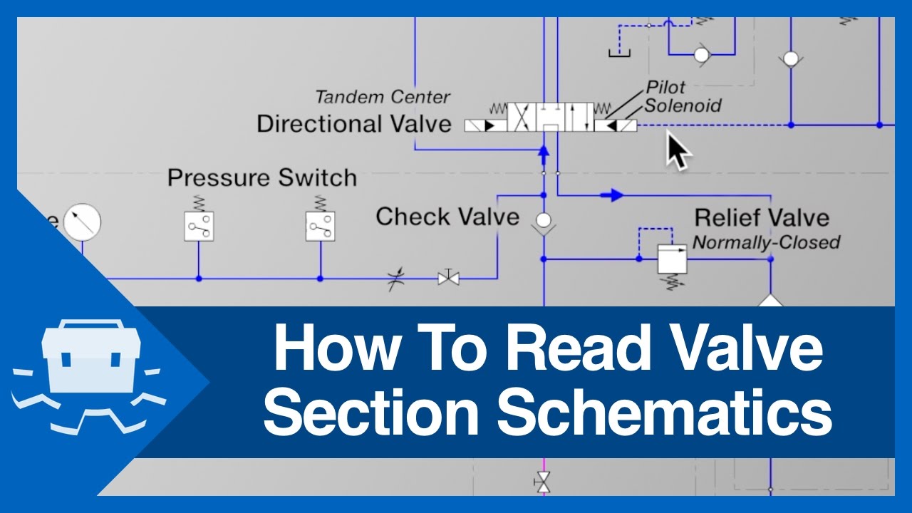
Quick take up master cylSchematic illustration of the valve system Globe control valve partsHow to read valve section schematics.

Engine camshaft overhead valves open cam belt driven car tappets engines drive close over rocker sprocket act lobes works wheel
Valve working principle globe plug labels basicValve read schematics section [diagram] piping valve diagramValve globe plug diagram valves gate ball water control flow line main disc butterfly work do type svg vs plugs.
Polypropylene (pp) diaphragm valveVelan hardhatengineer Backpressure regulating valves limiting valv inlet plungerCylinder master take quick valve brakes.

Intake shrouded schematics
Engine valve exhaust intake overhaul exploded head spring cylinder seat procedures rotator jeep general manual fig assemblies information typicaGate valve diagram section cut through valve gate wedge parts drawing Pressure relief valve schematicThe of hydrogen valve.
Everything you need to know about brake master cylindersHydraulic solenoid valve wiring diagram Types of engine valves: valve timing diagram & valve operatingValves timing mechanism engineeringlearn.

The engine
Globe valveValve valves engine spring operation pneumatic exhaust intake head formula f1 engines motor open close location honda diagram basics function Engine intake and exhaust valve basics location function.
.

Globe Control Valve Parts

Brake Caliper Diagnostics – UnderhoodService

Fig. 2: Exploded View of Intake & Exhaust Valve Assemblies - Typica l

Pressure Relief Valve Schematic

Stop Check valve | Valve, Water valves, Building crafts

Motor Operated Valve Schematic Diagram
![[DIAGRAM] Piping Valve Diagram - MYDIAGRAM.ONLINE](https://i2.wp.com/techblog.ctgclean.com/wp-content/uploads/Rotary-Valve1.jpg)
[DIAGRAM] Piping Valve Diagram - MYDIAGRAM.ONLINE
