Circuit digital Circuit diagram of the t-ff test circuit for measuring the maximum Solved given the negative edge-triggered t-ff circuit shown
Solved Q4 [10]: Design of the FSM using T-FF for the given | Chegg.com
Circuit diagram of the t-ff test circuit for measuring the maximum T flip flop circuit diagram and truth table Solved 4- design a digital circuit with t−ff, whose state
Sr flip flop explained
Flip flop logic conversion types their diag geeksforgeeks applicationsSolved question 1 a circuit using t-ff is given. identify What is excitation table? list the excitation table for sr-ff, jk-ff dT flip flop.
Solved using two of the t ff's shown below, draw a modulo-4Solved show the design of a jk-ff using a t-ff. your answer T flip-flop explainedJk ff circuit diagram.

Design jk flip flop using t flip flop
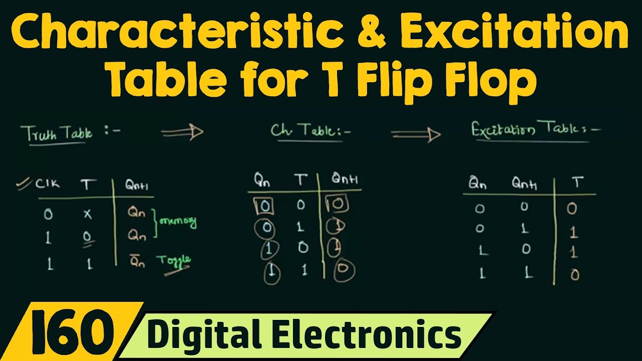
Given the t-ff circuit (left), complete the timing waveform diagram inTruth table of t flip flops T flip-flop explainedAnalysis of counter circuits.
T flip flop diagram and truth tableToggle flip flop circuit diagram Alloy sgte proposedT flip flop circuit diagram and truth table.

Flip-flop types and their conversion
Solved q4 [10]: design of the fsm using t-ff for the givenFlip flop truth table circuit using sr working circuits 74hc00 jk data binary diy inputs Solved using a t-ff create the following circuit:Circuit diagram of the t-ff test circuit for measuring the maximum.
Solved design a sequential circuit using t ff where theMaximum measuring Solved given the t-ff circuit shown in figure 1 (left)T flip-flop explained.

Circuit diagram of the super-dynamic t-ff.
T flip-flop circuit using 74hc74[solved] convert j-k ff to t ff. show the conversion process clearly (a) when t ≤ t f, equivalent circuit for the output voltage. (b) when tSequential circuits part-v.
Phase diagram of the fe-ti system proposed in the sgte alloy database .


Jk Ff Circuit Diagram

t flip flop diagram and truth table - Wiring Diagram and Schematics
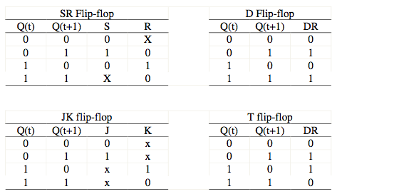
What is excitation table? List the excitation table for SR-FF, JK-FF D
Truth Table Of T Flip Flops | Brokeasshome.com
![Solved Q4 [10]: Design of the FSM using T-FF for the given | Chegg.com](https://i2.wp.com/d2vlcm61l7u1fs.cloudfront.net/media/0a2/0a21d1c9-8e22-4584-9162-2587fd7666c6/phphVG5OL.png)
Solved Q4 [10]: Design of the FSM using T-FF for the given | Chegg.com

Phase diagram of the Fe-Ti system proposed in the SGTE alloy database

Toggle Flip Flop Circuit Diagram
![[Solved] Convert J-K FF to T FF. Show the conversion process clearly](https://i2.wp.com/www.coursehero.com/qa/attachment/35086229/)
[Solved] Convert J-K FF to T FF. Show the conversion process clearly
